
GEOMETRICAL OPTICS
Light is the main focus of this unit.
We shall describe different phenomena of light such as reflection,
refraction, and total internal reflection. We will learn how images
are formed by mirrors and lenses and will discuss the working principles of compound
microscopes and telescopes.
REFLECTION
OF LIGHT:
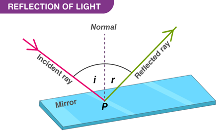
“When light traveling in a certain medium fall on the surface of another medium, a part of it turns back in the same medium.”
Reflection of light is shown in Fig.
When a ray of light from air falls on a plane mirror M, it is reflected. The
angle between the incident and normal N is called the angle of incidence
represented by i. The angle between the normal and the reflected ray is called the angle of reflection represented by r.
Incident Ray: The ray of
light coming from a source of light is known as the incident ray.
Reflected Ray: the light ray which is thrown back, when the incident rThe incident ray, the normal, and the reflected ray at the point of incidence all lie in the same plane
The angle of incidence is equal to the angle of reflection i.e., i = r.
Types of Reflection
The nature of reflection depends on the smoothness of the surface.
Regular reflection: The reflection of rays by smooth surfaces is called regular reflection.
For example, a smooth surface of silver
reflects rays of light in one direction only.
Irregular
reflection: The rough surfaces reflect the rays of
light in many directions. Such a type of reflection is called irregular
reflection. Most of the objects in the everyday world are not smooth on the
microscopic level.
SPHERICAL
MIRRORS

A spherical mirror is a mirror that has the shape of a piece cut out of a spherical surface. There are two types of spherical mirrors: concave, and convex.
In a spherical mirror, one of the two
curved surfaces is coated with a thin layer of silver followed by a coating of
red lead oxide paint. Thus, one side of the spherical mirror is opaque and the
other side is a highly polished reflecting surface. Depending upon the nature
of the reflecting surface, there are two types of spherical mirrors.
Concave Mirror: A spherical mirror whose inner curved
surface is reflected is called a concave mirror. In a concave mirror, the size of
the image depends on the position of the object. Both virtual and real images
can be formed by a concave mirror. Concave mirrors are also called
converging mirrors., therefore, it is called the real focus.
Convex Mirror: A spherical mirror whose outer curved
surface is reflecting is called a convex mirror. In a convex mirror, the size of the
image is always smaller than the object. Only virtual and erect image is formed
by a convex mirror. Convex mirrors are also called diverging mirrors.
“In
mirrors images are formed through reflection”
Mirror
Terminology
Pole: It is the midpoint of the curved surface of the spherical
mirror. It is also called a vertex.
Centre of Curvature (C): A spherical mirror is a part of a
sphere. The center of this sphere is called the center of curvature.

The radius of Curvature (R): It is the radius of the sphere of which the spherical mirror is a part.
Principal Axis: It is the line joining the center of
curvature and pole of the spherical mirror.
Principal focus (F): After reflection from a concave
mirror, rays of light parallel to the principal axis converge to a point F.
This point is called “The Principal Focus” of the mirror.
Focal length ( f ): It is the distance from the pole to
the principal focus measured along the principal axis. The focal length is
related to the radius of curvature by f =R/2. This means that as the radius of
curvature is reduced, so too is the focal length of the reflecting surface.
Characteristics
of Focus of a Concave and a Convex Mirror
|
Convex
Mirror |
Concave
Mirror |
|
The Focus lies behind the mirror |
The focus is on the front of the mirror |
|
The Focus lies behind the mirror The
focus is virtual as the rays of light after reflection appears to come from
the focus. |
The focus is real as the rays of
light after reflection converge at the focus. |
IMAGE LOCATION BY SPHERICAL
MIRROR FORMULA
“Mirror
formula is the relationship between object distance p, image distance q from
the mirror and focal length f of the mirror.”
Thus, we can write the mirror formula as
1/f = 1/p + 1/q _______ Eq 1
Eq
1 is true for both concave and convex mirrors. However, following sign
conventions should be followed to apply this equation for solving problems
related to mirrors.
Sign Conventions
|
Quantity |
When
Positive (+ ) |
When
Negative (– ) |
|
Object
distance p Image
distance q Focal
length f |
Real
object Real
Image Concave
mirror |
Virtual
object Virtual
image Convex
mirror |
REFRACTION
OF LIGHT
“The process of bending of light as it passes from air into glass and vice versa is called refraction of light.”

Example 1:
If we dip one end of a pencil or some
other object into the water at an angle to the surface, the submerged part looks
bent as shown in Fig. Its image is displaced because the light coming from the
underwater portion of the object changes direction as it leaves the water. This
bending of light as it passes from one transparent medium into another is
called refraction.
Example 2:

LAWS OF REFRACTION:
i.
The
incident ray, the refracted ray, and the normal at the point of incidence all
lie in the same plane.
ii.
The
ratio of the sine of the angle of incidence ‘i’ to the sine of the angle of
refraction ‘r’ is always equal to a constant i.e., sin i / sin r = constant = n
Snell's
law: The ratio Sin I / Sin r is
known as the refractive index of the second medium for the first
medium. So, we have
Sin I / Sin r = n
Speed
of light in a medium:
Refraction of light is caused by the
difference in speed of light in different media. For example, the speed of
light approximately in
Air =
3.0 × 10⁸ m s-1
Water =
2.3×10⁸ m s-1
Glass =
2.0 × 10⁸ m s-1
when light travels through a medium,
such as water or glass, its speed decreases. To describe the change in the
speed of light in a medium, we use the term index of refraction or
refractive index.
TOTAL
INTERNAL REFLECTION
When a ray of light traveling in a denser medium enters into a rarer medium, it bends away from the normal. If the angle of incidence ‘i’ increases, the angle of refraction ‘r’ also increases. For a particular value of the angle of incidence, the angle of refraction becomes 90o. The angle of incidence, that causes the refracted ray in the rarer medium to bend through 90o is called the critical angle. When the angle of incidence becomes larger than the critical angle, no refraction occurs. The entire light is reflected back into the denser medium. This is known as the total internal reflection of light.

APPLICATIONS
OF TOTAL INTERNAL REFLECTION
1.
Totally
Internal Reflecting Prism
A prism having an angle of 900 between its two refracting surfaces and
the other two angles each equal to 450, is
called a total reflecting prism. The light incident normally on any of its
faces, suffers total internal reflection inside the prism. Due to this behavior, a total reflecting prism is used
for the following three actions.

(a) To
deviate a ray of light through 900
(b) To
deviate a ray of light through 1800, and
(c) To
erect the inverted image without producing deviation in its path.
In the figure, it is an erecting prism that
is used to erect the inverted image without producing deviation in its path.
2.
Optical Fibre:
Total internal reflection is used in
fiber optics which has several advantages in the telecommunication field. Fiber
optics consists of hair-size threads of glass or plastic through which light
can be traveled. The inner part of the fiber optics is called the core that
carries the light and an outer concentric shell is called cladding. The core is
made from glass or plastic with a relatively high index of refraction. The cladding
is made of glass or plastic but of relatively low refractive index. Light
entering from one end of the core strikes the core-cladding boundary at an
angle of incidence greater than the critical angle and is reflected back into the
core. In this way, light travels many kilometers with a small loss of energy.

In Pakistan, optical fiber is being used
in telephone and advanced telecommunication systems. Now we can listen to thousands of phone calls without any disturbance.
3.
Light Pipe:
The light pipe is a bundle of thousands of
optical fibers bonded together. They are used to illuminate inaccessible
places by doctors or engineers. For example, doctors view the human
body. They can also be used to transmit images from one place to another.

“An endoscope is a medical instrument
used for exploratory diagnostics, and surgical purposes”
or
“An endoscope is used to explore the
interior organs of the body.”
Due to its small size, it can be
inserted through the mouth and thus eliminates invasive surgery. The
endoscopes used to examine the stomach, bladder, and throat are called
Gastroscopes, Cystoscopes, and Bronchoscopes respectively. An endoscope uses two fiber-optic
tubes through a pipe. A medical procedure using any type of endoscope is
called endoscopy. The light shines on the organ of the patient to be
examined by entering through one of the fiber tubes of the endoscope. Then the light is transmitted back to the physician’s viewing lens through the other
fiber tube by total internal reflection. Flexible endoscopes have a tiny camera
attached to the end. A doctor can see the view recorded by the camera on a
computer screen.

5.
REFRACTION
THROUGH PRISM
A prism is a transparent object (made of optical glass) with at least two polished
plane faces inclined towards each other from which light is refracted. In the case
of a triangular prism, the emergent ray is not parallel to the incident ray. It
is deviated by the prism from its original path. The incident ray PE makes an
angle of incidence ‘i’ at point E and is refracted towards the normal N as EF.
The refracted ray EF makes an angle ‘r’ inside the prism and travels to the
other face of the prism. This ray emerges out from the prism at point F making an
angle ‘e’. Hence the emerging ray FS is not parallel to the incident ray PE but
is deviated by an angle D which is called the angle of deviation.

LENSES
“A
lens is any transparent material having two surfaces, of which at least one is
curved.”
Lenses refract light in such a way that
an image of the object is formed. Lenses of many different types are used in
optical devices such as cameras, eyeglasses, microscopes, telescopes, and
projectors. They also enable millions of people to see clearly and read
comfortably.
Types
of Lenses
There are different types of lenses.
The lens which causes incident parallel rays to converge at a point is known as a convex or converging lens. This lens is thick at the center but thin at the
edges. Another type of lens causes the parallel rays of light to diverge from a
point. This is called a concave or diverging lens. This lens is thin at the
center and thick at the edges.
Lens
Terminology
Principal Axis: Each of the two surfaces of a
spherical lens is a section of a sphere. The line passing through the two
centers of curvatures of the lens is called the principal axis.
Optical Centre, C: A point on the principal axis at the
center of the lens is called the optical center
Principal
Focus, F: The light
rays traveling parallel to the principal axis of a convex lens after
refraction meets at a point on the principal axis, called principal focus or
focal point F. Hence, a convex lens is also called a converging lens. For a concave
lens, the parallel rays appear to come from a point behind the lens called
principal focus F (Fig. 12.21). Hence concave lens is also called a diverging
lens.
Focal
Length, f :

This is the distance between the optical center and the principal focus.
Power
of a Lens
“Power of a lens is defined as the
reciprocal of its focal length in meters.”
Thus, the Power of a lens = P =
The SI unit of power of a lens is
“Dioptre”, denoted by a symbol D. If f is expressed in meters so that
1 D = 1 m-1
Thus, 1 Dioptre is the power of a lens
whose focal length is 1 meter. Because the focal length of a convex lens is
positive, therefore, its power is also positive. Whereas the power of a concave
lens is negative, for it has a negative focal length.
IMAGE
FORMATION BY LENSES
In lenses, images are formed through refraction.
Image formation in convex lens with the
help of three principal rays:
1.
The
ray parallel to the principal axis passes through the focal point after
refraction by the lens.
2.
The
ray passing through the optical center passes straight through the lens and
remains un-deviated.
3. The ray passing through the focal point
becomes parallel to the principal axis after refraction by the lens.

Image Formation in Convex Lens

Figure: Image Formation in Convex Lens
|
Sr.
No |
Object
Position |
Image
Position |
Nature
of Image |
|
Case I |
At infinity |
At F |
real, inverted, and highly diminished |
|
Case II |
Object beyond 2F |
The image is between F and 2F |
real, inverted, and smaller than the
object. |
|
Case III |
Object at 2F |
The image is at 2F |
real, inverted, and the same size as the
object. |
|
Case IV |
The object between F and 2F |
The image is beyond 2F |
real, inverted, larger than the object. |
|
Case V |
Object at F |
No image is formed because the
refracted rays are parallel and never meet |
|
|
Case VI |
The object between the lens and F |
The image is behind the object |
virtual, erect, larger than the object. |
IMAGE
LOCATION BY LENS EQUATION
Let an object OP is placed in front of
a convex lens at a distance p. A ray PR parallel to the principal axis after
refraction passes through focus F. Another ray PC meets the first ray at point
P’ after passing through the optical center C. If this process is repeated for
the other points of the object, a real and inverted image O’P’ is formed at a
distance q from the lens.

p = Distance of object from the lens
q = Distance of image from the lens
f
= distance
between the lens and principal focus
Questions:
What is the size of the image formed in a
lens for a particular distance of the object from the lens?
What is the nature of the image, i.e.,
whether the image is real or imaginary, erect or inverted?
Lens formula
Lens formula is a tool that we use to
answer all such questions. We define lens as,
“The relation between the object and
image distance from the lens in terms of the focal length of the lens is called
lens formula.”
1/f = 1/p + 1/q _______ Eq 1
The above Eq is valid for both concave and
convex lenses. However, following sign conventions should be followed while
using this equation to solve problems related to lenses.
Sign Conventions for Lenses
Focal
length:
· f is positive for a converging lens
· f is negative for a diverging lens.
Object
Distance:
· p is positive if the object is
towards the left side of the lens. It is called a real object.
· p is negative if the object is on the
right side of the lens. It is called a virtual object.
Image
Distance:
· q is positive for an actual image made on
the right side of the lens by a real object.
· q is negative for a virtual image made
on the left side of the lens by a real object.
APPLICATIONS OF LENSES

1.
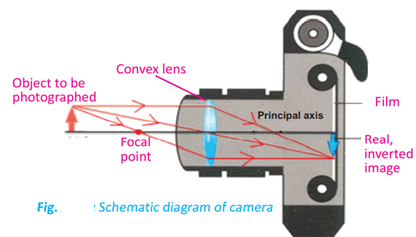
CAMERA
A simple camera consists of a
light-proof box with a converging lens in the front and a light-sensitive plate or
film at the back. The lens focuses images to be photographed onto the film. In a simple lens camera, the distance between lens and film is fixed which is equal
to the focal length of the lens. In the camera, the object is placed beyond 2F. A real,
inverted, and diminished image is formed in this way as shown in Fig.
2.
SLIDE
PROJECTOR
The light
source is placed at the center of the curvature of a converging or concave mirror.
The concave mirror is used to reflect light back in fairly parallel rays. The
condenser is made up of 2 converging lenses that refract the light so all parts
of the slide are illuminated with parallel rays.
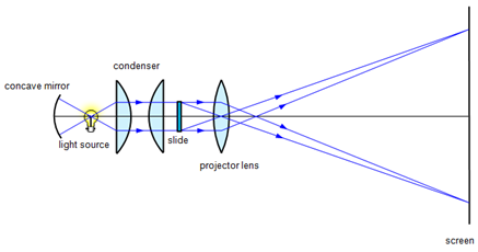
The
projection or converging lens provides a real, large and inverted image. It
must be real to be projected on a screen. The slide (object) must be placed
between F and 2F of the projection lens to produce a real, large, and
inverted image. Because the image is inverted, the slide must be placed upside
down and laterally inverted so we can see the image properly.
3.
PHOTOGRAPH
ENLARGER
In the case of the photograph enlarger object is placed at a distance of more than F but less than 2F. In this way, we get a real, inverted, and enlarged image as shown in Fig. The working principle of a photograph enlarger is basically the same as that of a slide projector. It uses a convex lens to produce a real, magnified, and inverted image of the film on photographic paper.

4.
SIMPLE
MICROSCOPE
A
magnifying glass is a convex lens that is used to produce magnified images of
small objects. Hence, it is also called a simple microscope. The object is placed nearer to the
lens than the principal focus such that an upright, virtual, and magnified image
is seen clearly at 25cm from the normal eye.
Magnifying
Power
Let be the angle subtended at the eye by a small object when it is placed at the near point of the eye (Fig-a). If the object is now moved nearer to the eye (Fig-b), the angle on the eye will increase and becomes, but the eye will not be able to see it clearly. To see the object clearly, we put a convex lens between the object and the eye, so that the lens makes a large virtual image of the object at a near point of the eye. In this way, the object appears magnified. The magnifying power, in this case, will be:

M = θ'/θ
M = 1 + d/f
here,
f = the focal length of the lens.
d = near the point of the eye.
It is clear from this relation that a
lens of a shorter focal length will have greater magnifying power.
Resolving
Power
The resolving power of an instrument is
its ability to distinguish between two closely placed objects or point sources.
To see objects that are close
together, we use an instrument of high resolving power. For example, we use a high-resolution power microscope to see tiny organisms and a telescope to view
distant stars.
5. COMPOUND MICROSCOPE
A compound microscope has two converging lenses, the objective, and the eyepiece, and is
used to investigate the structure of small objects.
some
features of the compound microscope:
§ It gives greater magnification than a
single lens.
§ The objective lens has a short focal
length, ƒo < 1 cm.
§ The eyepiece has a focal length, ƒe
of a few cm.
Magnification
of the Compound Microscope
Magnification can be determined through the ray diagram as shown in Fig.

The objective forms a
small image inside I1 the focal point of the eyepiece. This image acts
as an object for the eyepiece and the final larger image I2 is
formed outside the focal point of the objective. The magnification of a
compound microscope is given fo
M = L/fo ( 1+ d/fe )
Here,
L = the length of a compound microscope which is
equal to the distance between the objective and eyepiece,
d = distance of the final image from the eye,
fo = the focal lengths of the objective
fe = the focal lengths eyepiece.
Uses
of Compound Microscope
1.
A
compound microscope is used to study bacteria and other micro-objects.
2.
It
is also used for research in several fields of sciences like Microbiology,
Botany, Geology, and Genetics.
6. TELESCOPE
“Telescope
is an optical instrument used to observe distant objects using lenses
or mirrors. A telescope that uses two converging lenses is called a refracting
telescope.”
In
refracting telescope, an objective lens forms a real image of the distant
object, while an eyepiece forms a virtual image that is viewed by the eye.
WORKING ON REFRACTING TELESCOPE

The ray
diagram of refracting telescope is shown in Fig. When parallel rays from a
point on a distant object pass through an objective lens, a real image I1
is formed at the focus Fo of the objective lens. This image acts as
an object for the o eyepiece. A large virtual image of I2 or I1
is formed by the eyepiece at a large distance from the objective lens. This
virtual image makes an angle q at the eyepiece.
Magnification
of Telescope
Magnification of a refracting telescope
can be determined through the ray diagram in Fig. and is given by

7.
THE
HUMAN EYE
The image formation in the human eye is
shown in Fig. Human eye acts like a camera. In place of the film, the retina
records the picture. The eye has a refracting system containing a converging
lens. The lens forms an image on the retina which is a light-sensitive layer at the back of the eye. In the camera, the distance of the lens
from the film is adjusted for proper focus but in the eye, the lens changes focal
length. Light enters the eye through a transparent membrane called the cornea.
The iris is the colored portion of the eye and controls the amount of
light reaching the retina. It has an opening at its center called the pupil.
The iris controls the size of the pupil. In bright light, the iris contracts
the size of the pupil while in dim light pupil is enlarged. The lens of the eye
is flexible and accommodates objects over a wide range of distances.
Accommodation
The variation of the focal length of the eye
lens to form a sharp image on the retina is called accommodation.

Near
Point of Human eye:
“The
near point of the eye is the minimum distance of an object from the eye at
which it produces a sharp image on the retina.”
This distance is also called the least
distance of distinct vision. An object closer to the eye than the near
point appears blurred. For people in their early twenties with normal vision,
the near point is located about 25 cm from the eye. It increases to about 50 cm
at the age of 40 years and to roughly 500 cm at the of age 60 years.
Far
Point of Human eye:
“The far point of the eye is the
maximum distance of a distant object from the eye on which the fully relaxed
eye can focus.”
A person with normal eyesight can see
objects very far away, such as the planets and stars, and thus has a far point
located at infinity. The majority of people do not have “normal eyes” in this sense!
DEFECTS
OF VISION
“The
inability of the eye to see the image of objects clearly is called defect of
vision.”
The defects of vision arise when the
eye lens is unable to accommodate effectively. The images formed are therefore
blurred.
Nearsightedness
(myopia)
Nearsightedness (myopia) is a common vision condition in
which you can see objects near to you clearly, but objects farther away are
blurry.
Solution: The nearsighted eye can be corrected
with glass or contact lenses that use diverging lenses. Light rays from distant objects are now diverged by this lens before entering the eye. To the
observer, these light rays appear to come from a far point and are therefore
focused on the retina.

Farsightedness
(hypermetropia)
When a farsighted eye tries to focus on
a book held closer than the near point, it shortens its focal length as much as
it can. However, even at its shortest, the focal length is longer than it
should be. Therefore, the light rays from the book would form a blurred image
behind the retina
Solution: This defect can be corrected with the
aid of a suitable converging lens. The lens refracts the light rays and they
converge to form an image on the retina. To an observer, these rays appear to
come from a near point to form a sharp virtual image on the retina.

CONCEPTUAL QUESTIONS
12.1.
A man raises his left hand in a plane mirror, the image facing him is raising
his right hand. Explain why.
Ans: A man
raises his left hand in a plane mirror; the image facing him is raising his
right hand. Because light rays are
reflected in a mirror causing us to
see an inverted image
12.2.
In your own words, explain why light waves are refracted at a boundary between
two materials.
Ans: Light
waves are reflected at a boundary between two materials due to a change in the speed
of light while traveling from one
medium to another. This change in speed of light at the boundary is caused by
the change in the refractive indices of two materials.
12.3.
Explain why a fish underwater appears to be at a different depth below the
surface than it actually is. Does it appear deeper or shallower?
Ans: A fish underwater appears to be shallower
than it really is, because
of apparent depth, as a virtual image
is formed at I above O, where the image seems to be formed
due to refraction of light.
12.4.
Why or why not concave mirrors suitable for makeup?
Ans: Concave mirrors
are suitable for makeup as they act as magnifiers
to form large size erect images of objects. When a
person stands between the principal focus and the pole of the mirror
12.5.
Why is the driver's side mirror in many cars convex rather than plane or
concave?
Ans: The driver’s side mirror is convex as it gives an upright,
erect although small image, it provides a wider field of view as it is curved outwards.
12.6.
When an optician's testing room is small, he uses a mirror to help him test the
eyesight of his patients. Explain why.
Ans: To increase
the distance of alphabets, from the patient,
the optician uses a plane mirror
if his testing room is small.
12.7.
How does the thickness of a lens affect its focal length?
Ans: If the thickness of a lens is
increased; the power of the lens is also increased. Hence the focal length
of the lens is decreased.
12.8.
Under what conditions will a converging lens form a virtual image?
Ans: Converging lens forms a virtual image when the object is placed between the optical
center and its focal point.
The image formed will be erect and larger than the object
12.9.
Under what conditions will a converging lens form a real image that is the same
size as the object?
Ans: When an object is placed at 2F from the converging lens it forms a real and inverted
image that has the same
size as the object.
12.10.
Why do we use a refracting telescope with a large objective lens of large focal
length?
Ans: In refracting telescope, we use an objective lens of a larger focal length to gather more light from weak distant sources. It not only makes them
more visible but also increases the resolving power of the telescope.


